C-Board
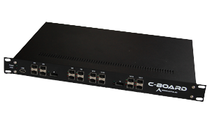
The SCALOPES C-board is a programmable, 10 Gb/s Ethernet-capable, FPGA-based device from AITIA. It has been developed to host services and applications for high speed networks. The user-defined logic running on the FPGA can realize a wide range of networks applications such as traffic filters, firewalls, monitoring probes, traffic generators, routers and switches with programmable capabilities. The SCALOPES C-board
- is programmable in hardware and software,
- can manipulate the traffic through PCIe-connected controllers,
- has capabilities to directly forward 10Gb/s Ethernet traffic to/from 1Gb/s Ethernet or SONET/SDH,
- is designed for measurable low power consumption,
- has lowered risks for extra developments since composability, predictability and dependability issues are tackled by design.
Architecture
The SCALOPES C-board occupies a standard 1U x 19 inch rack mount case, with active cooling on redundant power supplies, and passive cooling on board. Network interface connectors are mounted on front; management, and mains connectors are on the rear panel. The main part of the hardware is the FPGA ring, containing four FPGAs (Virtex 5, XC5VLX110T). The external interfaces (SFP, XFP and PCI-E slots) connect to the FPGA’s RocketIO ports, which allow high-speed communication between interfaces. Further variation of interfaces (Gigabit fiber, 10/100 Ethernet, STM-1 optic etc…) is possible by using SFP module receivers.
Interfaces
Front mounts:
- 2 XFP module receptacle for 10 Gb/s Ethernet,
- 16 SFP module receptacle for 1G/100M/10 Ethernet (half of them are available for Multistandard / Multirate applications).
- 2 USB host connectors (+1 internal for booting a pen-drive, and 4 more on pin headers),
- 1 RJ45, 10/100 Ethernet for management LAN,
- 2 DB9 for RS232 console connection.
- 4 SODIMM200 receptacle for 1.8V DDR2 SDRAMs,
- 1 Express Card module receptacle,
- 1 COM (Computer On Module) Express receptacle.
The FPGA-ring
The FPGA-based networking cores are tied onto a Gigabit bi-directional ring, implementing 2x14 Gb/s backplane capacity (ClockWise, and AntiClockwise). This bi-directional ring is made especially visible in the architectural figure. In addition, a TDM local bus is available for handling exceptions, traps, and out-of-band signaling-data, as well as clock synchronization.
The physical and logical connection between the interfaces is defined by the FPGA firmware ensuring the hardware’s flexibility. The current firmware is stored on flash memory connected to the chips: they load as soon as the hardware starts.
There are four FPGA cores on the board: one Management Host Core (MHC), two Multi-Standard Cores (MSC), and one Switch Core (SWC).
- The Management Host Core (MHC) can be used to connect the ring to a management PC (COM Express module) for managing the C-BOARD and terminating network services.
- The Multi-Standard Cores (MSC) can be used as media Gateways and to integrate legacy network links into a modern core network. SDH based TUG/POS/ATM carriers are supported.
- The Switch Core (SWC) is a generic part of the ring - implementing router functions beyond tagged switching, and MPLS.
Computer On Module
The management computer of the C-board is implemented using COM Express Type-1 (or higher) child board, running Linux operating system.
Application features
- 64 bit Timestamp with 4/8 nsec resolution,
- lossless packet capture limited only by host PC's speed and resources,
- header-only capture: configurable protocol layer depth decoded by hardware on-the-fly,
- fully PCAP/WINPCAP compliant interface,
- parameterized line speed capable packet/flow generator for active measurements,
- RFC 2544 tester implementation
